Navigate
Products
Download
eShop
Upgrade
Overview
Training
Support
Navigate
Products
Download
eShop
Upgrade
About
Training
Support
The Auto Outliner commend allows to create double-layered outlines for single object or multiple objects (fig. 1.). Objects may overlap or intersect one another and program creates outlines only for the visible parts. It is useful for creation of outlines like shown on the right picture (fig. 2.).

Fig. 1. Overlapping objects to be outlined.

Fig. 2. Double layered outline.
Select objects you want to outline and click the ![]() button, or use main menu > Transform > Auto Outliner
command. This will create a number of small outline elements like shown on below picture (fig. 3.). All outline
elements have color of the first object (orange, in this case). Select new color from palette and draw it to selection
to change color of the outline elements (fig. 4.).
button, or use main menu > Transform > Auto Outliner
command. This will create a number of small outline elements like shown on below picture (fig. 3.). All outline
elements have color of the first object (orange, in this case). Select new color from palette and draw it to selection
to change color of the outline elements (fig. 4.).

Fig. 3. Number of outline elements created by auto outliner.
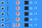
Fig. 4. Outline elements with new color.
Use ![]() button or main menu > Transform > Arrange Outline Parts command
to order and combine elements into continuous double layered outline (fig. 5). Note that this function will connect all
elements into single object by inserting connections where it is necessary (fig. 6.). If you want free standing objects
like outlines of holes to be left unconnected, use main menu > Transform > Arrange Outline Parts (no
Connections) command instead.
button or main menu > Transform > Arrange Outline Parts command
to order and combine elements into continuous double layered outline (fig. 5). Note that this function will connect all
elements into single object by inserting connections where it is necessary (fig. 6.). If you want free standing objects
like outlines of holes to be left unconnected, use main menu > Transform > Arrange Outline Parts (no
Connections) command instead.
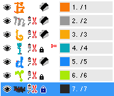
Fig. 5. Complete outline created with 'Arrange Outline Parts' command.

Fig. 6. Outline of hole connected to the main outline.
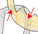
Fig. 7. Hidden parts are not outlined.
On places where one object lays on top of the other, automatic outlines are created only for those parts that are on top of the others. Program automatically ignores hidden parts (fig. 7. , marked by red arrows)
Please note: auto outliner can fail to work properly on places where edge of one object runs (almost) on top of edge of other object, i.e. parts of their edges are almost identical. On such places, outliner may generate large amount of small outlines, because nearly identical edges intersect each other on many places. Common designs have either separate or overlapped areas and such situation does not occur. In most cases the problem occurs when vector graphics (EMF, WMF or CMX files) is used, because graphic files are created in a different way (no overlays, many identical edges).