Navigate
Products
Download
eShop
Upgrade
About
Training
Support
Navigate
Products
Download
eShop
Upgrade
About
Training
Support
The main menu > Import Vector File function opens the vector graphic file and converts it into the embroidery design automatically. It is intended to avoid redrawing of design (logo or clipart) in Studio if it is already available in a vector file. This function is available only if user has registered Font Engine plug-in.
There are many graphic programs that produce various vector file formats and most of them can export vector graphics into SVG, WMF or EMF files. SVG and EMF is more advanced than WMF and it can store color palette and curve objects too. It is recommended to convert graphics to SVG format directly from the native vector format of the respective graphic program (Corel Draw CDR, Adobe Illustrator AI and so on). Conversion to WMF (older format) and then from WMF to SVG (new format) may cause the degradation of the graphics.
SVG and EMF file can contain various objects (raster bitmap, fonts, shapes, curves, polygons, etc.). However, Studio can import only the curves, all other objects are ignored. To achieve best results, please convert all objects like fonts and shapes to curves before attempting to import the SVG file into Studio.
If there is a bitmap picture in the file, Studio ignores it. It does not auto digitize the picture. Only the vector (curves) objects are transformed into embroidery objects.
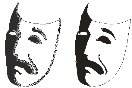
Note: not all vector files can be converted into good quality embroidery designs. Some vector files may be auto-traced from scanned pictures and resulting vector file can have thousands of tiny objects instead of low number of solid fills or smooth lines. Such vector files are not proper for conversion into embroidery designs.

Left-side picture is poor quality vector graphics composed of thousands of small objects auto-traced from scanned picture.
Right-side picture is good quality vector graphics with low number of large solid areas.
Design imported from vector file usually needs some adjustments of stitching parameters and/or object layout.

Design imported from EMF vector files. Stitches are not generated yet.
After importing of design, select all objects and use Generate Stitches command. Studio analyzes the shape and size of individual objects and fills them appropriate fill type. However, it cannot identify the meaning of vector objects like human digitizer. For example, program cannot identify objects that belong to the lettering and it may fill each letter with other style, according to this letter size or width. Thin elongated objects are filled with auto-column (wider objects have pattern). Large objects use plain fill, either vertical or horizontal, according to their shape.

Design with generated stitches.
All objects are filled with auto-column, but some have also a pattern texture.
The pattern is applied to wider objects (magenta arrow) to split too long
stitches.
Green arrow marks the white fill of bird that would look better with
plain fill instead of auto-column.
User may need to adjust the fill type parameters. In this case, the length of stitches is near the threshold that turns on the pattern. This is the reason why some letters have pattern and some do not. We should either turn-on or turn-off the pattern for all letters. For later option, select the letters E, m and r and open the Parameters window.

Turning off the pattern option of auto-column fill in Parameters window.

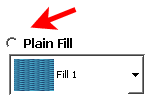
Turning on the plain fill mode instead of auto-column mode for white fill of the bird.

New parameters applied to stitches. All letters use satin
auto-column stitches without pattern.
White fill of bird is now a plain fill, not auto-column.
It is important to pay attention to layers and overlays of objects imported from vector files. Unlike graphic, embroidery is very sensitive to use of layers. On places with multiple layers (overlays), the stitches are sewn on top of the previous stitches and may spoil the embroidery if density becomes to high.
You should visually check the overlapped areas for too many layers. The largest part of design should be single layer only. Where different objects overlap, try to keep 2 layers overlay on most places, or 3 layers overlay maximum if it is not possible to avoid it.
Layers in this case mean dense cover stitching, not underlays or connection paths. Underlay is loose stitching that helps to stabilize the design against thread pull and push effect, but it does not contribute to overall density very much. Connections are stitch paths (often hidden beneath the other objects) used to avoid trims between objects. Both underlays and connections can be regarded as layers, but they are usually not significant when investigating density of cover layers.

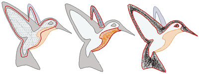
Illustration of overlays in imported design.
Left: white fill (highlighted) sticks out under the black, orange and blue
objects.
Center: orange and blue objects (highlighted) overlap the white fill.
Right: black objects (highlighted) overlap the white fill and on a very small
area also the blue and orange objects.
Missing or very small overlay is an error just as the too heavy overlay. Pull of the thread causes gaps between objects on places with insufficient overlay.
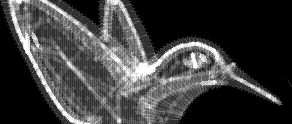
If there are too many layers or too large overlays in the design, they should be removed or edited to achieve good sew-out of design. Studio provides a quick way to check the density of stitches. Use tabs at bottom of the Studio screen to switch to D-map (density map) or X-ray view mode to analyze the density layout. Stitches must be generated first, otherwise these view modes do not work.

The X-ray view mode allows to detect areas of critical (too high) density.
Please note: it is also possible to export design from Studio to graphic vector format to avoid redrawing of design in graphic software. Please use main menu > Design > Export command.